STATIC ANALYSIS FOR A TEMPORARY TENSILE-STRUCTURE
DESIGNED FOR TRAVELLING SHOWS
Author: Andrea Angeleri, freelance
ABSTRACT
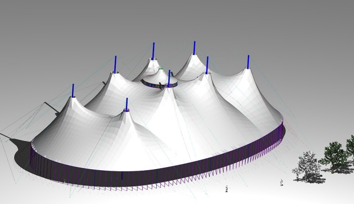
The construction is a prestressed 8-masts shaped membrane structure, designed to be used for travelling shows (no permanent installation allowed). It’s realised by means of a pre-tensioned single-skin membrane (divided in 10 sectors) supported in the centre by an 8.5m diameter cupola, and sustained by 8 masts, and tensioned at the perimeter by tied-down side posts. The membrane is the waterproof covering element and transmits loads to the structure (cupola + masts + up-winding cables) which supports it. The tensioned structure is closed on the sideways by side walls 5.0m tall.
The Big Top has been calculated for TEMPORARY use by adopting ASCE 7-10 wind loading standards as the guideline for wind pressure calculations.
Covered surface: 2.820 m2 -
Surface of membrane: 3.750 m2
1. APPLIED STANDARDS
The standards to which we make reference are the following:
Eurocode 3 - "Design of steel structures" - ENV 1993-1-1.
EN 13782/05 - "Temporary structures - Tents - Safety"
2004 TensiNet - The European Design Guide for Tensile Surface Structures -
edited by Brian Forster, Marijke Mollaert.
CNR UNI 10011 / 88
Steel constructions: instructions for calculation, realisation, test and
maintenance.
Project of Italian norm UNI U50.00.299.0 - 11/96
Tents, tensile structures, air-supported structures: instructions for
calculation, realisation, test, use and maintenance.
DIN 4112 /83 Fligende Bauten
Temporary structures: instructions for calculation and construction.
Eurocode 1 - Basi di calcolo ed azioni sulle strutture UNI ENV 1991-2-4
Parte 2-4: Azioni sulle strutture - Azioni del vento.
American Society of Civil Engineers - ASCE 07/10
Minimum Design Loads for Buildings and Other Structures
2. MATERIALS
2.1. Membrane:
polyester fabric coated PVC - type 2
tensile strength w/w (N/5 cm): 4000/4000 (DIN 53354) = 80 / 80 kN/m
The membrane is simulated as an orthotropic material i.e. a material that
has different properties and stiffness values in each perpendicular
directions. The assumed material properties are the followings:
Young's modulus along warp direction = E1 = 600 daN/cm = 600 kN/m
Young's modulus along weft direction = E2 = 600 daN/cm = 600 kN/m
Shear Moduli = G12 = 35 daN/cm = 35 kN/m
Poisson's ratio 12 = 21= 0,5
2.2 Nuts & bolts
Screw 8.8 (Fyk = 649.0 N/mm2), nuts S6; galvanization required.
2.3 Cables
Type S10 - 216 threads 6x36 galvanized Warrington Seale cables 6 x 36 + WR
right cross-shaped - UNI ISO 2408.
- CUPOLA SUSPENSION CABLES - S10 ZN diam.16mm (MBL = 192 kN)
- MAST RING SUSPENSION CABLES - S10 ZN diam.18mm (MBL = 243 kN)
- MAST TIE-DOWN CABLES- S10 ZN diam.16mm (MBL = 192 kN)
- MAST CONNECTING CABLES (diam.12mm S10ZN - MBL = 108 kN)
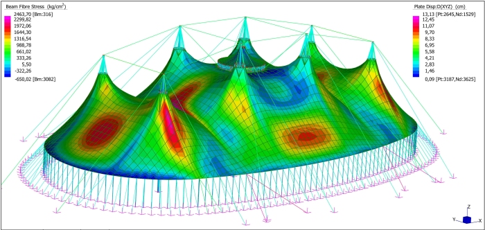
The membrane geometry has been shaped starting from the plan and altimetric disposition agreed with the client using a graphic interactive program of calculation which allows to investigate the initial condition (status 0), realising a mathematical model and imposing equilibrium to a system of trusses and nodes. The structural model has been then analysed to find generated stresses and deformations with the FEM method using the software Straus7 (certified by STRAND7) with a non-linear static analysis.
The membrane is realised with a polyester fabric high tenacity coated PVC type 2, reinforced in the top part to resist local stress concentrations. The membrane joints have been realised by means of welding presses with an high-frequency system which makes the material melt with an automatic control system of power. Weldings are tested at 70° C, critic state of the membrane exposed to sun radiations.
|
The construction is a prestressed 8-masts shaped membrane structure, designed to be used for travelling shows (no permanent installation allowed). It’s realised by means of a pre-tensioned single-skin membrane (divided in 10 sectors) supported in the centre by an 8.5m diameter cupola, and sustained by 8 masts, and tensioned at the perimeter by tied-down side posts. The membrane is the waterproof covering element and transmits loads to the structure (cupola + masts + up-winding cables) which supports it. The tensioned structure is closed on the sideways by side walls 5.0m tall. The Big Top has been calculated for TEMPORARY use by adopting ASCE 7-10 wind loading standards as the guideline for wind pressure calculations. |
|
1. APPLIED STANDARDS |
|
The membrane geometry has been shaped starting from the plan and altimetric disposition agreed with the client using a graphic interactive program of calculation which allows to investigate the initial condition (status 0), realising a mathematical model and imposing equilibrium to a system of trusses and nodes. The structural model has been then analysed to find generated stresses and deformations with the FEM method using the software Straus7 (certified by STRAND7) with a non-linear static analysis. The membrane is realised with a polyester fabric high tenacity coated PVC type 2, reinforced in the top part to resist local stress concentrations. The membrane joints have been realised by means of welding presses with an high-frequency system which makes the material melt with an automatic control system of power. Weldings are tested at 70° C, critic state of the membrane exposed to sun radiations. |